Is bottles per hour enough to select a filling center?
No. Output must be tied to a reference bottle, while product conditions, neck and cap, format changes, water supply, bottle transfer, cleaning and downstream discharge also need confirmation.
XGF water filling machine selection
Compare the XGF rinsing-filling-capping range on a 500 ml reference basis, then verify the bottle, water, closure, utilities and downstream interfaces that determine the final machine.
Direct answer
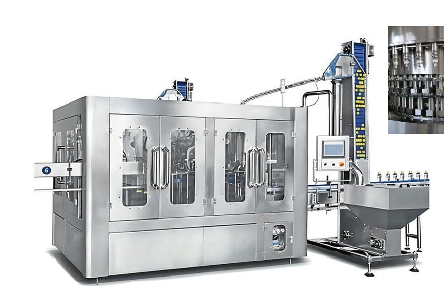
An XGF bottled water filling machine combines bottle rinsing, normal-pressure filling and capping in one monoblock. The verified reference family shown here includes nine models from 6,000 to 42,000 bottles per hour on a 500 ml basis for nominal container sizes from 500 to 2,000 ml. Final selection still requires the bottle and neck drawing, cap, treated-water conditions, required saleable output, utilities, downstream equipment and an agreed test method.
XGF filling platform reference
The XGF family combines bottle rinsing, normal-pressure filling and capping in one monoblock. The published reference range covers 6,000–42,000 bottles per hour for 500 ml bottles, with container sizes from 500–2,000 ml.
| Model | Capacity BPH, 500 ml |
Machine size L × W × H, mm |
Weight kg |
Installed power kW |
|---|---|---|---|---|
| XGF14-12-5 | 6,000 | 2,360 × 1,770 × 2,700 | 2,800 | 2.42 |
| XGF16-16-5 | 8,000 | 2,760 × 2,060 × 2,700 | 3,800 | 3.12 |
| XGF24-24-8 | 13,000 | 2,800 × 2,230 × 2,700 | 4,800 | 3.92 |
| XGF32-32-8 | 16,000 | 4,215 × 2,960 × 2,700 | 5,800 | 4.92 |
| XGF40-40-12 | 18,000 | 4,360 × 3,300 × 2,700 | 6,800 | 7.30 |
| XGF50-50-15 | 24,000 | 5,900 × 4,123 × 2,700 | 8,600 | 7.87 |
| XGF60-60-15 | 30,000 | 5,770 × 5,288 × 2,700 | 10,800 | 11.00 |
| XGF72-72-18 | 36,000 | 6,540 × 4,900 × 2,700 | 12,800 | 11.40 |
| XGF80-80-18 | 42,000 | 7,800 × 6,380 × 2,700 | 15,000 | 15.37 |
Selection note. These are filler-platform reference ratings, not a guarantee of complete-line saleable output. Bottle geometry, water conditions, cap, downstream equipment, utilities, changeovers and the agreed test method can change the final selection.
Request a Model & Line ReviewSystem focus 01
Bottles enter from an air conveyor and are transferred through the rinsing, filling and capping zones before controlled discharge. Combining the three functions reduces intermediate bottle handling, but the monoblock still depends on correctly defined bottle, water and closure conditions.
System focus 02
Bottle geometry and neck handling affect the rinser, transfer stars, guides and air-conveyor infeed. The published platform references nominal containers from 500 to 2,000 ml, with bottle height and diameter limits that must be checked against final drawings and samples.
System focus 03
The filler needs stable treated-water quality, flow, pressure and temperature conditions together with compatible cap handling. Tanks, pumps, cap elevators and any project-specific closure treatment provisions must be reviewed as part of the filling center.
System focus 04
The reference platform describes OMRON PLC control, inverter coordination and photoelectric operating-status detection. These controls support machine coordination, but the final order still needs an approved component list, control narrative, signal schedule, safety review and destination-specific electrical confirmation.
System focus 05
Sealed bottles need controlled discharge, inspection and useful accumulation before labeling and packing. A 42,000 BPH filler nameplate does not guarantee 42,000 saleable bottles per hour when treatment, bottle supply, utilities or end-of-line equipment cannot sustain the same reference condition.
Filling-center interfaces
Performance depends on the received bottle, water and closure conditions and on controlled bottle discharge.
| Handover | Inputs to define | What to verify |
|---|---|---|
| Bottle infeed | Drawing, neck, formats, rate and transfer method | Stable arrival and compatible handling parts |
| Product-water feed | Quality, flow, pressure, temperature and tank/pump boundary | Controlled filling conditions throughout the test |
| Closure supply | Cap drawing, material, feed orientation and treatment scope | Reliable feeding, application and closure checks |
| Sealed-bottle discharge | Bottle state, conveyor, inspection and buffer controls | No structural downstream restriction at the reference rate |
Buyer questions
Use these answers as a project-planning starting point. Final equipment and performance remain subject to the confirmed brief.
No. Output must be tied to a reference bottle, while product conditions, neck and cap, format changes, water supply, bottle transfer, cleaning and downstream discharge also need confirmation.
The direct interfaces normally include treated-water delivery, bottle infeed, closure handling, cleaning provisions, controls and the sealed-bottle discharge conveyor.
Useful accumulation can absorb short labeler or packer interruptions. Without coordination, downstream stops repeatedly interrupt the filling center and reduce usable line output.
Deep technical guides
Each guide answers one narrower project question and links the result back to complete-line scope.
Cap treatment must match the approved closure, product-risk assessment, filling concept and validated operating method while preserving feeding and sealing performance.
Bottle rinsing is a controlled preparation step whose method, medium and evidence should follow the incoming container and filling-system risk assessment.
An inspection station protects production only when it detects a defined condition, tracks the correct bottle and confirms that nonconforming product is controlled.
Reliable capping begins with a qualified cap and neck combination, then protects closure identity and orientation from bulk loading through application, inspection and reject response.
Low fills, overfills, foaming and bottle-to-bottle variation may come from product supply, container geometry, filling components, machine condition or the way results are sampled, so the pattern matters more than a single bottle.
A leaking or difficult-to-open water bottle may reflect the cap, bottle finish, feed path, capping head, container support, fill condition or test method, so torque alone should never be treated as the complete diagnosis.
An inspection plan connects each material or process risk with a measurable characteristic, a suitable detection point and a defined response.
A high machine rating does not show whether the filler can be cleaned, inspected and maintained without exposing product or open bottles.
Replacing a seal can change fill behavior or introduce contamination when valve identity, parts, assembly and release evidence are not controlled.
Rotary and linear water fillers should be compared on the approved container range, saleable output, hygiene boundary, changeover pattern, footprint and service model. Machine architecture affects accumulation, access and future expansion; neither format is universally best.
Gravity and pressure filling choices depend on product characteristics, target fill, container behavior, required output and hygienic control. Still water often suits atmospheric principles, but the correct valve and bowl design must follow the actual product and package duty.
Allot Tech project desk
Share the source water, bottle, target output, pack format, factory status and destination. We will use them as the basis for a project-specific configuration discussion.