Approved materials
Control the combinations the system must process.
- Cap and neck drawings with revisions
- Approved physical samples and suppliers
- Bottle support and stiffness context
- Tamper and liner requirements
- Color and material identity rules
Treat closure handling and application as one controlled path
Reliable capping begins with a qualified cap and neck combination, then protects closure identity and orientation from bulk loading through application, inspection and reject response.
Direct answer
Provide controlled bottle-neck and cap drawings, approved samples, closure materials, tamper features, color variants, required application condition and the complete format list. Define how caps arrive, the replenishment method, acceptable accumulation, feeder location and environmental controls. Require a clear route from hopper to orienter, elevator, chute, cap transfer and application head, with sensors and responses for low supply, jams, missing caps and downstream stops. Acceptance should challenge each agreed cap-and-bottle combination and inspect application outcomes using project-approved methods. Capper settings or motor torque alone cannot establish finished-closure integrity.
System focus 01
A cap described only by nominal diameter is not a complete input. Obtain the controlled closure and neck-finish drawings, approved supplier samples, material, liner condition where applicable, tamper-band geometry, application guidance and permitted variation. Record bottle stiffness and support at capping because the container must withstand application without distortion. If several colors or cap suppliers will be used, define how identity and comparability are controlled. The machine supplier should identify the exact format parts, application components and trials needed for every proposed bottle-cap pair, including any combination that has not yet been validated.
System focus 02
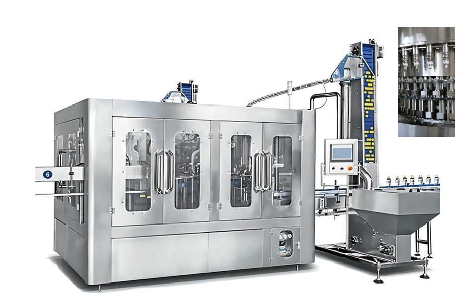
Define whether caps arrive in sealed bags, cartons or returnable containers and where primary packaging is opened. The feeder arrangement should limit unnecessary exposure, prevent foreign material from entering and allow controlled removal of spilled or damaged closures. Usable hopper volume and replenishment interval should reflect bulk behavior at the target demand. Review operator reach, lifting, tipping and platform access, especially where an elevator serves a high capper. The proposal should show how caps are oriented, how incorrectly oriented items return or discharge, and how the path is accessed for cleaning without introducing uncontrolled contamination.
System focus 03
A correctly oriented cap can still be damaged or lost if chute pressure, cap release and bottle timing are not controlled. Define the chute route, full and low-level detection, buffer between the orienter and capper and response when the filler stops. At the application point, review bottle support, cap pickup or placement, head type, speed matching and adjustment method. Settings should be controlled by format and supported by an approved inspection method. If application force or torque is monitored, distinguish machine-setting data from a finished-container measurement made with the agreed instrument and timing.
System focus 04
Specify which conditions the machine detects: low caps, no cap at transfer, missing closure after application, raised or skew cap, jam or application-head fault may require different devices. A detector must have a defined line response, reject mechanism or hold procedure, and downstream tracking distance. Challenge tests should verify not only detection but also the disposition of the affected bottle. Agree how production made between the last acceptable check and a confirmed fault is identified. Vision or sensor capability should be described by the configured characteristic; it should not be presented as proof of every seal or product-safety attribute.
System focus 05
List caps and bottles by format, then identify change parts, recipes, adjustments, tools and reference settings. Operators need safe access to the feeder, elevator, chute, transfer and application heads for inspection and removal of cap dust or fragments. Maintenance documentation should cover wear components, head service, sensors and recommended spares without implying a universal replacement interval. Acceptance should use approved closures from the intended supply, run start-stop and low-cap events, verify alarms and inspection responses, and examine finished samples against an agreed plan. Site checks should repeat critical interfaces after installation and actual material supply.
Closure system inquiry pack
Use all three groups so a feeder quote is not separated from application and inspection requirements.
Control the combinations the system must process.
Trace caps from sealed supply to bottle application.
Verify configured functions with representative materials.
The agreed inspection plan and controlled bottle-cap pair define closure acceptance; a capper setting alone is not a finished-package guarantee.
Buyer questions
Use these answers as a project-planning starting point. Final equipment and performance remain subject to the confirmed brief.
Only after the alternative caps are shown to be compatible with the approved neck, feeder, chute and application equipment. Dimensional and material variation can change feeding or closure results, so each controlled source should be reviewed and tested.
No. Machine settings, application-head behavior and finished-bottle measurements are related but not interchangeable. Define the finished-closure test method, instrument, sampling time and acceptance basis with the cap, bottle and quality teams.
The choice depends on cap packaging, consumption, floor layout, operator work, contamination controls and access. A hopper with elevator can reduce manual lifting at height, but the complete replenishment, guarding and cleaning route still needs review.
No. It checks a configured visible or sensed condition. Closure application, tamper feature, leak behavior and other quality attributes may need additional inspection or sampling under the approved quality plan.
Deep technical guides
Each guide answers one narrower project question and links the result back to complete-line scope.
Cap treatment must match the approved closure, product-risk assessment, filling concept and validated operating method while preserving feeding and sealing performance.
A leaking or difficult-to-open water bottle may reflect the cap, bottle finish, feed path, capping head, container support, fill condition or test method, so torque alone should never be treated as the complete diagnosis.
Capacities, process routes, layouts, utilities and equipment shown on this site are decision frameworks and reference examples. They are not a final specification, performance guarantee or offer. Confirmed scope and performance are defined in the signed technical and commercial agreement.
Allot Tech project desk
Share the source water, bottle, target output, pack format, factory status and destination. We will use them as the basis for a project-specific configuration discussion.