Krones Modulfill VFJ water filler
Official manufacturer reference used to understand a current water-filling valve principle. The selected machine manual, not this source, controls maintenance steps and limits.
Treat each valve intervention as precision and hygiene work
Replacing a seal can change fill behavior or introduce contamination when valve identity, parts, assembly and release evidence are not controlled.
Direct answer
Use the exact filler model, valve drawing, OEM manual and site safety and hygiene procedures. Identify the affected valve and symptom, preserve fill-level or other process evidence, isolate every energy and product source, and release the machine for work. Disassemble in a controlled clean area using identified tools and part locations. Inspect seals, springs, stems, seats, guides, vents and actuating components against OEM criteria; do not invent wear limits or interchange similar-looking parts. Reassemble with approved components, orientation, lubrication and tightening method, then complete leak, motion, timing and filling checks under the approved protocol. Clean or sanitize the opened hygienic boundary as required and record valve identity, findings, parts, settings, tests and authorized production release.
System focus 01
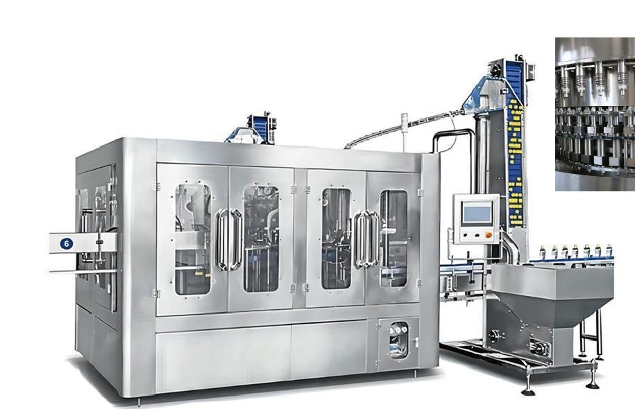
A rotary filler can contain many similar valves, but the correct task depends on the filling principle and exact assembly. Record machine, carousel and valve position, product and format, alarm, fill result, leak location, event timing and recent maintenance. Compare the symptom across neighboring valves to separate one-valve behavior from bowl pressure, product supply, bottle lift, recipe or broader timing problems. Review the current OEM drawing and parts list before authorizing disassembly so the team does not use a generic procedure on a different revision.
System focus 02
Stop the filler using the approved sequence and isolate electrical, pneumatic, hydraulic, pressure, gravity and stored mechanical energy as applicable. Drain and secure the product circuit under the site procedure. Protect nearby open product-contact components and identify every removed part, tool, wipe and temporary cover. Define where cleaned parts can be placed and how replacements enter the zone. Maintenance access does not itself release the line from food-safety controls; coordinate maintenance, operations and quality roles before opening the valve.
System focus 03
Clean parts using the approved method before judging their condition. Inspect seals for damage, swelling, hardening or incorrect profile; inspect seats, stems and guides for wear, deposits or scoring; and check springs, actuators and vents for condition and free movement. Measurements require suitable instruments and documented limits from the OEM or approved engineering disposition. Record the actual finding rather than writing “worn” without evidence. If repeated damage appears at the same location, investigate alignment, bottle contact, chemistry, pressure, installation and task method before repeatedly replacing parts.
System focus 04
Verify each replacement part by controlled number, material and revision rather than visual similarity. Keep seals and product-contact parts protected until installation. Follow the defined assembly sequence, orientation, approved lubricant where allowed, adjustment and tightening method. Avoid transferring a neighboring valve setting without confirming the design and reference. Mark any changed setting and preserve removed parts when investigation requires it. Conduct a peer or independent check for critical orientation, retention and tool removal before guards or product circuits are closed.
System focus 05
Restore services in the approved sequence and check for leaks or abnormal motion at safe conditions. Exercise the valve and relevant actuation, then perform cleaning or sanitation required by the opened hygienic boundary. Run representative bottles under a controlled test that checks fill result, valve timing, leakage, bottle handling and any applicable inspection signal. Compare with the agreed specification and neighboring valves without assuming one sample is sufficient. Quality and operations should release production only after records, part reconciliation and affected-product controls are complete.
Valve work record
Use the exact OEM task and project procedures; this matrix organizes the record without replacing either.
| Work gate | Evidence required | Decision | Record |
|---|---|---|---|
| Diagnose | Valve ID, symptom and operating conditions | Open valve or investigate system first | Approved work scope |
| Inspect | Clean component and OEM criterion | Reuse, replace or escalate | Finding and part disposition |
| Assemble | Approved parts, sequence and settings | Accept independent check | Assembly and configuration record |
| Release | Function, hygiene and fill test | Return to production or contain | Signed maintenance and quality release |
Never infer tolerances, tightening values, seal materials or service intervals from a generic web guide.
Editable buyer worksheet
Capture as-found condition, OEM instruction, parts, reassembly, sanitation, functional checks and release evidence valve by valve.
Technical reading
Confirm the standards, guidance and legal requirements that apply to the project location and product before final design.
Official manufacturer reference used to understand a current water-filling valve principle. The selected machine manual, not this source, controls maintenance steps and limits.
Official manufacturer reference used for the maintenance-planning and equipment-lifecycle context; the exact filler manual controls valve work and limits.
Primary United States safety reference for energy control during servicing; applicable destination and site procedures may be different or additional.
Buyer questions
Use these answers as a project-planning starting point. Final equipment and performance remain subject to the confirmed brief.
Use the OEM guidance, operating hours or cycles, water and cleaning duty, inspection findings, failure history and condition evidence. A universal interval could cause unnecessary intervention or allow an unsuitable task to run too long.
Only when the approved parts documentation confirms compatibility for that model, valve revision, product and cleaning duty. Similar appearance or nominal size is not sufficient evidence.
Possible sources include valve parts, restriction, timing, bottle lift, venting, sensor or broader product-supply conditions. Preserve evidence and compare neighboring valves before assigning a cause.
No. The release plan may also require actuation, timing, cleaning or sanitation, representative filling, repeatability, inspection-system and quality checks under defined conditions.
Capacities, process routes, layouts, utilities and equipment shown on this site are decision frameworks and reference examples. They are not a final specification, performance guarantee or offer. Confirmed scope and performance are defined in the signed technical and commercial agreement.
Allot Tech project desk
Share the source water, bottle, target output, pack format, factory status and destination. We will use them as the basis for a project-specific configuration discussion.