Process and material view
Confirm what moves through the plant.
- Water and bottle process sequence
- Packaging and consumable routes
- People, sample and maintenance access
- Reject, waste and quarantine paths
- Finished-pack storage and dispatch
Turn equipment scope into a workable factory arrangement
A useful water bottling plant layout coordinates production flow, hygiene, utilities, access, maintenance, storage and dispatch. It cannot be selected from bottles per hour or one generic floor-area number.
Direct answer
Plan a water bottling plant layout by first mapping the actual water, bottle, closure, label, packing, people, waste and finished-goods flows. Place confirmed equipment footprints and service clearances on a measured building survey, then add utility rooms, quality areas, material and finished-product storage, access, lifting, drains, ventilation, sanitation provisions and emergency routes. Review hygiene and incompatible crossings before freezing the line direction. The final area comes from a controlled room-and-function schedule plus approved equipment drawings, not a universal square-metre allowance.
System focus 01
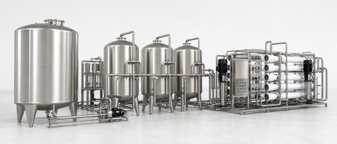
Start with the material and process sequence that the factory must support. Raw water or product water, preforms or purchased bottles, caps, labels, film or cartons, rejected material, cleaning supplies, laboratory samples, operators, maintenance parts and finished packs do not all use the same route. Show entry, storage, preparation, production, hold, release and dispatch points. This exposes crossings and missing areas before a visually tidy machine row is mistaken for a complete plant layout.
System focus 02
The layout should support the hygienic controls established for the selected product and destination. Separate incompatible movements and provide controlled access to product-contact or container-preparation areas where required. Locate handwashing, changing, cleaning-material storage, sampling and sanitation support according to the site plan. Avoid assuming that painted lines alone create hygienic separation; walls, doors, airflow, drainage, procedures and supervision may all affect how the designed zones work in operation.
System focus 03
A supplier footprint shows only part of the space a machine needs. Add operator positions, guarding and door swings, electrical-panel access, mold or format-part removal, filter and pump service, conveyor adjustment, lubrication, inspection, cleaning and safe component replacement. Check columns, clear height, floor condition, loading, pits, overhead services and escape routes. Confirm how the largest shipping split reaches its installed position without removing completed building work.
System focus 04
Power, high- and low-pressure air, cooling, process water, cleaning water, drainage, ventilation and any heat rejection need routes as well as capacities. Place connection points to avoid unsafe hoses, inaccessible valves, electrical-water conflicts or long uncontrolled product circuits. Show distribution responsibility and elevation, not only a utility-room label. Drain locations and floor falls should follow actual discharge and cleaning needs while remaining accessible for inspection and maintenance.
System focus 05
List production, utilities, raw and packaging materials, quality, maintenance, staff facilities, finished goods, dispatch, waste and future expansion as separate functions with their assumptions. Reconcile the schedule with the measured building and equipment layout. Issue drawings with revision, date, scale, equipment references and open points. When a bottle, machine, pack pattern or utility changes, review affected routes and clearances before construction or installation proceeds from an obsolete plan.
Layout release checklist
The process, building and execution views should describe the same project before site work is treated as final.
Confirm what moves through the plant.
Confirm what the site can support.
Confirm how the plan will be delivered.
Qualified local building, fire, food-safety, environmental and occupational professionals must confirm requirements that apply to the actual site.
Technical reading
Confirm the standards, guidance and legal requirements that apply to the project location and product before final design.
Primary US overview used to keep sanitary facilities, operations, source protection and testing visible in the factory-planning discussion.
Intergovernmental hygiene reference supporting a connected review of source, processing, containers, facilities and finished-product handling.
Buyer questions
Use these answers as a project-planning starting point. Final equipment and performance remain subject to the confirmed brief.
There is no reliable universal area. It depends on treatment, bottle route, capacity, equipment footprints, pack format, storage policy, utilities, quality areas, access, maintenance, dispatch and expansion. Build an area schedule from the confirmed scope.
No. Straight, L-shaped or other arrangements can work when transfers, access, utilities, hygiene, building limits and finished-pack flow are coordinated. The best direction depends on the actual building and equipment.
Early planning can proceed with documented allowances, but final foundations, connections, heights, access and service clearances should use approved equipment information and controlled revisions.
Provide a measured plan with columns, doors, heights and services; approved equipment footprints; material and finished-pack flows; utility information; storage assumptions; access routes; and the intended expansion boundary.
Deep technical guides
Each guide answers one narrower project question and links the result back to complete-line scope.
Environmental monitoring supports verification of hygienic controls when sampling locations, methods, trends and actions are connected to the actual filling-room risks.
A HACCP plan is a site-specific control system developed by a qualified team, not a generic list of critical control points copied from another bottling plant.
Hygienic zoning should control how water, containers, closures, people, tools, air, waste and cleaning activities move around the points where product and package are exposed.
Drainage planning must account for routine process water, concentrated treatment residuals, cleaning events, spills and abnormal releases whose peak flow and composition can differ sharply.
A production-line schedule is credible when it links information, engineering, manufacturing, factory preparation and acceptance through named gates and responsible owners.
Site acceptance demonstrates the delivered line in its destination environment after installation and commissioning prerequisites are stable enough for a controlled test.
Conveyors are a dynamic interface system: they must move empty and filled bottles without instability, damage, contamination risk or repeated starvation and blocking.
Ventilation and heat-load planning should protect people, equipment, hygiene and stable production across the bottling hall, compressor room, blowing area and chemical spaces. Generic air-change rates cannot replace a zone-by-zone sensible, latent and contaminant load analysis.
Capacities, process routes, layouts, utilities and equipment shown on this site are decision frameworks and reference examples. They are not a final specification, performance guarantee or offer. Confirmed scope and performance are defined in the signed technical and commercial agreement.
Allot Tech project desk
Share the source water, bottle, target output, pack format, factory status and destination. We will use them as the basis for a project-specific configuration discussion.