Minitab cap removal torque data example
Statistical software source confirming cap-removal torque as continuous process data; the example values are not used as product specifications.
Closure process control
Cap torque SPC distinguishes a stable closure-application process from random measurement noise and special causes; it does not turn an arbitrary torque target into a valid closure specification.
Direct answer
First define the exact bottle finish, cap, liner or linerless design, capper head and approved application and removal-torque methods. Control tester calibration, sample conditioning, opening speed, delay after application and operator technique. Collect rational subgroups that preserve head, time and operating-state identity, then select a chart suited to the data and subgroup structure. Establish control limits from stable process behavior; keep them distinct from engineering specification limits. A reaction plan should identify the suspected head and product boundary, verify the measurement system, contain potentially affected bottles, investigate cap, finish, chuck, setup and environmental causes, and require evidence before restart.
System focus 01
Torque has meaning only for a specified closure system and test condition. Record bottle finish drawing, cap design and lot, liner where used, application equipment, head identity, product and relevant temperature or conditioning. Distinguish application torque, dynamic removal torque and other supplier-defined tests; they are not interchangeable numbers. Obtain acceptance requirements from the approved closure-system specification and verified technical sources. Also define the quality outcome that torque helps protect, such as seal integrity, tamper-band performance and consumer opening, while recognizing that torque alone does not prove every outcome.
System focus 02
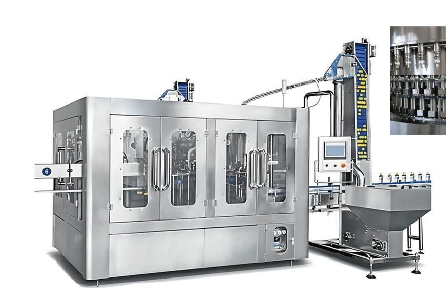
Variation from the tester and operator can obscure the capper signal. Use a suitable calibrated instrument with fixtures that hold the bottle without distorting it. Standardize the interval between capping and measurement, sample temperature and conditioning, opening direction and speed, peak-reading rule and handling of tamper-band effects. Train analysts and periodically examine repeatability and reproducibility for the intended range. Protect samples from manual tightening or loosening. Record damaged bottles, slipped fixtures and interrupted tests as invalid observations with reasons; do not quietly replace inconvenient values.
System focus 03
A sample plan should reveal the failure mode rather than blend it away. Select bottles close enough in time to describe short-term behavior, but preserve capper-head identity so one weak or over-tightening head is not averaged with the others. Rotate coverage across all heads and include defined checks after start-up, adjustment, stoppage, cap-lot change or maintenance. Use a chart type appropriate to individual values or subgrouped continuous data and confirm its assumptions. The plant statistician or qualified quality engineer should approve the method; copying a chart template without understanding subgroup structure can create false alarms or miss real shifts.
System focus 04
Control limits describe the expected spread of a stable process under the chosen chart; specification limits describe acceptable product requirements. One cannot be substituted for the other. Establish trial limits only from data judged stable and representative, then investigate special-cause signals such as a point beyond a limit or a nonrandom run according to the approved rules. Capability analysis is meaningful only after stability, measurement adequacy and a justified distribution approach have been assessed. A process can be stable but unable to meet the closure specification, or unstable while most current results still sit inside specification.
System focus 05
When a chart signals or a specification result fails, pause affected output as required, verify the tester and examine whether the signal is head-specific, material-specific or common to the machine. Identify the last verified acceptable condition and hold the credible production interval. Check cap feed, chuck wear or cleanliness, head height, spring or magnetic settings, bottle finish, cap dimensions, line speed and relevant environment using controlled instructions. Adjustments need authorization and recorded before-and-after evidence. Restart with targeted samples that demonstrate the signal has cleared, then monitor subsequent production and investigate any affected product separately.
SPC reaction matrix
The pattern determines containment, measurement checks and technical investigation.
| Observed pattern | First verification | Likely scope | Next evidence |
|---|---|---|---|
| One head shifts | Tester and head identity | Head-specific time window | Chuck, setting and finish checks |
| All heads shift | Method and common materials | Common production interval | Cap lot, height, speed and environment |
| High random spread | Measurement repeatability | Method or mixed causes | Fixture, handling and head-stratified data |
| Stable but off specification | Limit sources and method | System capability | Engineering correction and validation |
Use qualified statistical review and the approved closure-system specification. This matrix does not prescribe torque values, sample size or control-chart constants.
Editable buyer worksheet
Record conditioned samples, measurement system, capper head, project-supplied limits, control signals and reaction evidence.
Technical reading
Confirm the standards, guidance and legal requirements that apply to the project location and product before final design.
Statistical software source confirming cap-removal torque as continuous process data; the example values are not used as product specifications.
International technical reference used for control-chart, process-stability and specification distinction principles.
Instrument-provider reference used for repeatable torque-test method considerations; current closure specifications remain authoritative.
Buyer questions
Use these answers as a project-planning starting point. Final equipment and performance remain subject to the confirmed brief.
There is no universal value. Use the approved bottle-finish and closure-system specification, cap supplier and equipment technical evidence, verified test method and relevant validation. A number from another cap diameter, resin, liner or test delay can be unsafe and misleading.
No. Control limits are calculated from stable process data to detect unusual variation. Specification limits come from the approved engineering and quality requirement. The process must be both statistically understood and capable of meeting the separate product requirement.
Individual heads can wear, become dirty or drift differently. Pooling all results can conceal a localized defect or prompt unnecessary adjustment of the whole capper. Head identity makes containment and root-cause work more precise.
No. Torque is one process indicator. Seal outcome also depends on cap and finish geometry, liner or sealing surfaces, damage, contamination, application alignment and distribution conditions. Combine torque control with appropriate leak, visual and tamper-evidence verification.
Capacities, process routes, layouts, utilities and equipment shown on this site are decision frameworks and reference examples. They are not a final specification, performance guarantee or offer. Confirmed scope and performance are defined in the signed technical and commercial agreement.
Allot Tech project desk
Share the source water, bottle, target output, pack format, factory status and destination. We will use them as the basis for a project-specific configuration discussion.