Operating model
Describe how supply and demand change over time.
- Treatment inflow by operating state
- Filler demand by bottle format
- Required interruption coverage
- Low-demand turnover strategy
- Start-up, stop and restart sequence
Protect treated water between the last process and the filler
The product-water tank and filler-feed loop are active process interfaces, not passive capacity: their design influences turnover, pressure stability, cleaning access and restart behavior.
Direct answer
Specify the system from a time-based operating model. Define the incoming treatment flow, filler demand by format and state, permitted storage window, planned stops and sanitation sequence. Then establish tank working volume, level bands, vent treatment, circulation route, pump duty, filler inlet condition, instruments, alarms, drains and cleaning boundaries. The supplier should show how the system behaves during normal demand, treatment interruption, filler stop, restart and cleaning. Acceptance needs evidence of hydraulic stability, level control, drainability and agreed cleaning functions at the installed interfaces; a nominal tank volume alone does not establish a hygienic or reliable feed system.
System focus 01
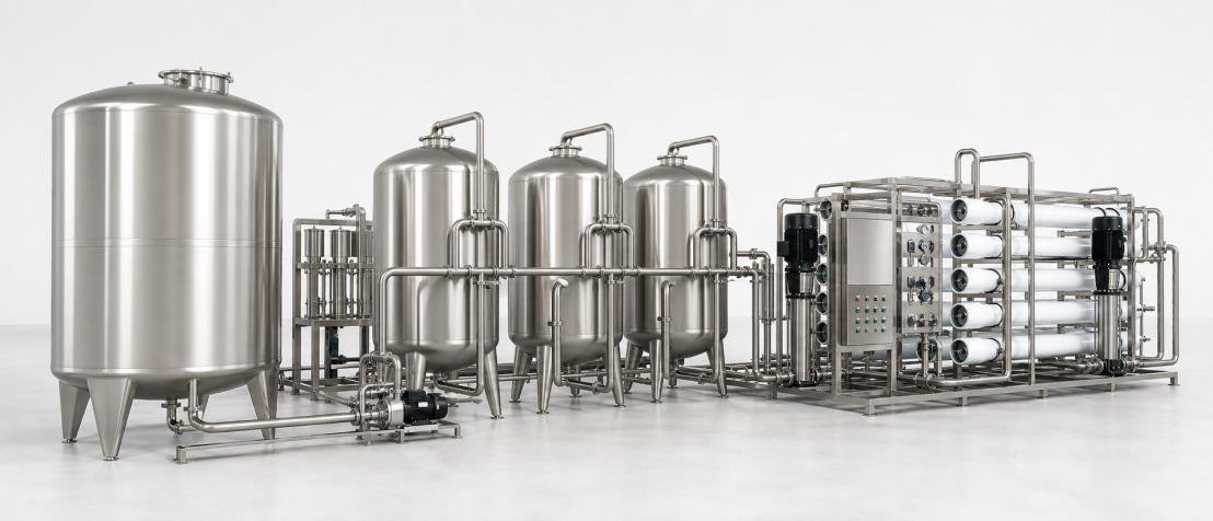
Start by marking where treated water becomes product water and where responsibility transfers to the filler. List every tank connection, return line, sample point, instrument branch, overflow, vent, drain and chemical or rinse connection. Unused branches and ambiguous tie-ins can become difficult-to-clean hold-up locations. Materials, surface condition and connection type should follow the confirmed product and site design basis rather than a generic description. The interface drawing should also identify who supplies and installs interconnecting pipework, supports, insulation if required, valves, cables and field instruments.
System focus 02
A larger tank offers more time between supply and demand, but it also increases residence time and may complicate cleaning. Build a simple time balance using treatment inflow, filler draw, minimum operating level, maximum control level and the events the tank is intended to bridge. Separate geometric volume from usable working volume and unavailable level near outlets or overflow. Review slow production days as well as peak demand, because poor turnover can be hidden by a capacity calculation. The final volume should reflect a documented operating and sanitation plan, not a rule based only on hourly filler capacity.
System focus 03
The filler supplier should provide required inlet pressure, flow range, connection, temperature limits and response to low supply. Size the feed pump and pipe route for dynamic conditions, including friction loss, valves, filters or final treatment and any return flow. Check minimum tank level for suction conditions and define protection against dry running or unsuitable pressure. Where variable-speed control is used, document the pressure sensor location, control band and response to filler start, stop and demand changes. A large motor or pump nameplate does not prove a stable hygienic handover at the filler connection.
System focus 04
Level measurement connects the treatment train to filling. Define which level starts and stops treatment, enables the feed pump, warns the operator and protects against overflow or low-level operation. The control narrative should address signal failure, maintenance override, power recovery and communication loss rather than only normal automatic mode. If recirculation or a final treatment stage is included, show its operating states when the filler is stopped. Instrument selection and installation must allow calibration and maintenance without creating undocumented product-water paths or unsafe intervention.
System focus 05
Agree whether the tank and loop are cleaned by a dedicated circuit, a wider plant system or a manual procedure, and identify every supply and return boundary. Review spray-device coverage where applicable, drainability, vent and overflow treatment, removable components, inspection access and the route for displaced liquid. Acceptance can include fabrication records, component verification, control simulation, drainage observation and an installed cleaning sequence using the agreed method. Microbiological claims require a defined sampling and validation program; they should not be inferred from material names or a brief water run.
Storage and feed design brief
A complete inquiry connects tank capacity with its flow paths, controls, cleaning method and filler handover.
Describe how supply and demand change over time.
Define every wet-side component and connection.
Agree what can be checked before and after installation.
Hygienic performance depends on the installed system, approved procedures and verification program; it cannot be guaranteed by tank volume or material description alone.
Buyer questions
Use these answers as a project-planning starting point. Final equipment and performance remain subject to the confirmed brief.
There is no universal multiple of filler capacity. Calculate usable volume from treatment inflow, filler demand, intended interruption coverage, level bands, turnover, cleaning schedule and restart strategy. Review both peak-demand and low-demand periods before fixing the tank size.
Recirculation can reduce stagnation and support an integrated treatment concept, but it does not replace suitable tank design, controlled vents, cleanable piping, sanitation procedures, monitoring and verification. Flow paths and return conditions must be engineered for the actual system.
No. Selection also needs inlet-pressure requirements, piping and equipment losses, minimum tank level, suction conditions, control method, demand variation and cleaning duty if shared. Confirm the operating point with the pump and filler suppliers.
Evidence may include design review, material and fabrication records, access and drainability checks, functional cleaning tests and site verification under an approved sanitation plan. The necessary evidence depends on the project; a polished material description alone is insufficient.
Deep technical guides
Each guide answers one narrower project question and links the result back to complete-line scope.
A product-water recirculation loop should preserve the approved water condition from hygienic storage to the filler during production and idle states. Pipe geometry, return route, tank behavior, pump control and sanitation must be designed together.
A product-water booster system should supply the filler with stable pressure and flow while preserving hygienic condition across tank level, line-rate and stop-start changes. Pump curve, control valve or VFD, recirculation and filler dynamics must be considered together.
Capacities, process routes, layouts, utilities and equipment shown on this site are decision frameworks and reference examples. They are not a final specification, performance guarantee or offer. Confirmed scope and performance are defined in the signed technical and commercial agreement.
Allot Tech project desk
Share the source water, bottle, target output, pack format, factory status and destination. We will use them as the basis for a project-specific configuration discussion.