Cloudiness, pearlescence, uneven walls, weak bases, distorted necks and unstable bottle transfer can share visible symptoms while arising from very different material, heating, air, mold, cooling or handling conditions.
How should a team troubleshoot PET bottle blowing defects?
Start by defining the exact defect, affected locations, first occurrence and pattern by cavity, time and material lot. Place the blower in the approved safe state before inspecting any hot, pressurized or moving area. Hold the approved bottle and preform specification constant, then isolate preform condition, utilities, tooling, recipe identity and downstream handling one category at a time. Measure actual evidence against approved project records rather than changing several settings together. After a qualified person corrects the confirmed cause, repeat a controlled run, inspect a representative sample and verify transfer through the filler interface before closing the record.
System focus 01
1. Define the bottle defect before touching the process
Use precise observations instead of the broad statement that bottles are bad. Record whether the issue is haze, whitening, incomplete formation, off-center gates, base rocking, neck damage, panel distortion, wall variation, leaks or poor conveyor stability. Mark the physical location on a bottle drawing and retain labeled samples. Determine whether every cavity is affected, one cavity repeats the issue, the condition drifts after startup, or the defect follows a preform lot. Note the approved bottle format, mold set, recipe identity, operator, time and downstream observation. This symptom map narrows the search and prevents an adjustment from hiding a material or tooling problem.
Photograph and label representative acceptable and defective bottles
Map the defect by cavity, bottle zone, time and material lot
Record the approved format, mold, recipe and startup state
Separate cosmetic observations from dimensional, leak or transfer failures
Preserve samples before any process change is made
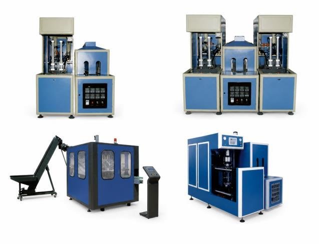
Reference equipment image. The final equipment selection, configuration and safeguards depend on the confirmed project brief.
System focus 02
2. Make the blower safe and protect the production area
A stretch blow molding system combines hot surfaces, closing molds, high-pressure air, stored pneumatic energy and automatic handling. Stop work and follow the machine-specific isolation procedure before entering guarded areas, approaching a mold, opening an air circuit or inspecting an oven. Only trained and authorized personnel should perform technical checks. Never bypass a guard, interlock, pressure device or alarm to observe a cycle. Identify bottles that may be structurally weak and contain them so they cannot enter filling or packing. If the issue could affect container integrity or product protection, keep the affected production segregated until the authorized quality function defines its disposition.
Use the approved shutdown and energy-isolation procedure
Allow hot components to reach a safe inspection condition
Keep guards, interlocks and pressure protection fully functional
Quarantine bottles made since the last confirmed acceptable check
Escalate damaged tooling, abnormal noise or air leakage to qualified staff
System focus 03
3. Isolate preform, utility, tooling and handling inputs
Hold the approved bottle target constant while checking each input family. Confirm the preform part, neck finish, mass basis, color, storage history, cleanliness and lot change. Verify that the selected mold and change parts match the format and that visible surfaces, vents and cooling connections are in their documented condition. Review high- and low-pressure air, cooling water, electrical supply and ambient conditions at the defined connection points, using the equipment documentation rather than a generic target. Finally inspect bottle discharge, cooling time, guides and air conveyor behavior because a correctly formed bottle can be distorted or marked after leaving the mold. Change only a controlled variable after evidence identifies it.
Match the preform lot and specification to the approved bottle
Confirm mold, neck handling and change-part identity
Check air, cooling and power conditions at named boundaries
Inspect discharge, conveyor contact and downstream back pressure
Record any recent material, maintenance or recipe change
System focus 04
4. Measure the pattern against approved process evidence
Convert the symptom map into measurements suited to the defect. Depending on the approved inspection plan, this may include bottle dimensions, standing stability, neck condition, wall distribution, section weight, visual transmission, leak behavior or functional passage through handling equipment. Correlate results with cavity, production time and utility trends. Compare actual recipe identification and displayed conditions with the approved setup record; do not infer a new temperature, pressure, timing or stretch setting from a generic article. Inspect maintenance history for heaters, sensors, valves, seals, molds and cooling circuits. The objective is to show one plausible cause with evidence strong enough for a qualified correction, not to adjust until the sample happens to look better.
Use calibrated or verified inspection methods where required
Plot measurements by cavity and time instead of averaging them away
Compare actual records with the approved setup and maintenance history
Check whether the defect follows a utility event or material change
Document the evidence that supports and rejects each suspected cause
System focus 05
5. Correct one confirmed cause and retest the complete handover
Have an authorized technician correct the evidenced cause under the machine manual and approved change-control process. Restore guards, utilities, recipe controls and housekeeping before restarting. Use identified preforms and the normal downstream path, then collect samples across cavities and across enough production time to detect recurrence. Repeat the same dimensional, visual and functional checks used to define the problem. Confirm that bottles cool, transfer, rinse, fill, cap, label and pack without a new instability; a bottle that passes a bench check may still fail at the next interface. Record the correction, results, rejected alternatives and monitoring plan. Close the issue only when the agreed acceptance evidence is complete.
Authorize and record the specific corrective action
Restore all safeguards before controlled production resumes
Sample every relevant cavity and more than one time interval
Repeat the original inspection method on the new samples
Verify bottle transfer and downstream processing before release
Bottle defect diagnostic path
Move from a visible defect to a verified cause
Keep the approved bottle specification fixed and preserve evidence through each diagnostic gate.
1. Describe the symptom
Label samples and map the bottle zone, cavity, time, lot and downstream effect.
2. Establish a safe state
Isolate stored energy under the machine procedure and contain potentially weak bottles.
3. Separate the inputs
Review preform, tooling, utility, recipe and handling changes without altering several factors.
4. Measure the evidence
Use approved dimensional, visual and functional checks and correlate results by cavity and time.
5. Correct and verify
Authorize one supported correction, repeat the inspection and prove downstream handover.
Machine manuals, approved recipes, risk controls and project specifications govern all work. This sequence does not supply operating setpoints or authorize access to hazardous areas.
Buyer questions
Frequently asked questions
Use these answers as a project-planning starting point. Final equipment and performance remain subject to the confirmed brief.
Why should several blower settings not be changed at once?
Multiple simultaneous changes destroy cause-and-effect evidence and can introduce a second defect. Hold the approved basis stable, identify a supported cause and let qualified personnel change one controlled factor.
Can a bottle look acceptable but still cause production problems?
Yes. Neck geometry, wall distribution, base stability or cooling state may affect conveying, filling, labeling or packing even when a quick visual check appears acceptable.
Does a defect limited to one cavity always mean mold damage?
No. A repeating cavity pattern narrows the investigation, but heating, stretching, valves, cooling, venting, sensors and handling also require evidence-based checks before a cause is assigned.
What evidence should remain after the issue is closed?
Keep identified samples or photographs, the symptom map, input and utility records, measurements, authorized correction, retest results, product disposition and any follow-up monitoring action.
Continue planning
Related production-line decisions
Move to the technical decision that depends on the information covered on this page.
Review wear items, planned work and controlled spare-part replacement.
Project-specific confirmation
Capacities, process routes, layouts, utilities and equipment shown on this site are decision frameworks and reference examples. They are not a final specification, performance guarantee or offer. Confirmed scope and performance are defined in the signed technical and commercial agreement.
Allot Tech project desk
Turn your requirements into a comparable line brief.
Share the source water, bottle, target output, pack format, factory status and destination. We will use them as the basis for a project-specific configuration discussion.